
GenTemP 500 Low Ambient Kit Installation Instructions
Please Note* Installation is to be performed by qualified, licensed personnel in accordance with all national, state and local codes. Please read completely through the instructions before proceeding.
Installation procedures as follows:
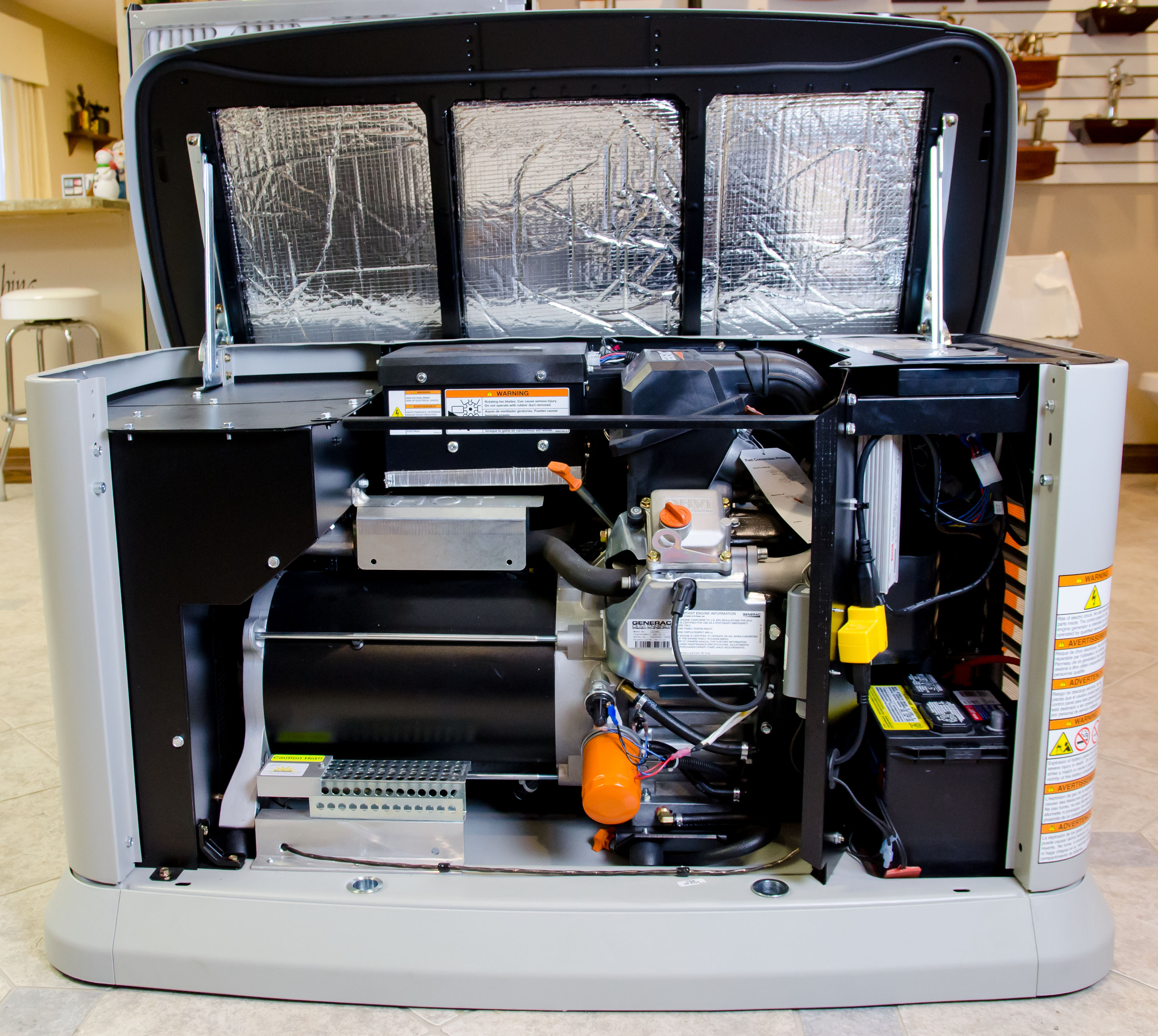
- Raise the lid and turn the generator system control switch to off.
- Remove generator front panel cover to access the battery and engine compartments.
- Remove all contents of the GenTemP low ambient kit from the box.
These include:- (1) Prewired Heat Module and Thermostat Assembly
- (1) Battery Pad Heater
- (1) 1 ¼” Wiring Grommet
- (4) ¼” x ½” Hex Head Self-Tapping Screws to attach Thermostat and (2) Wire Looms
- (3) ¼” x ¾” Hex Head Self-Tapping Screws to attach Heat Module
- (2) 1-Hole Wire Looms
- (1) 6” Zip Tie and Zip Tie Bracket with Phillips Head Self-Tapping Screw
- (1) 36” Female Cord
- (1) Universal Fuse Holder Assembly
- (1) Easy Heat High Limit Safety Stat
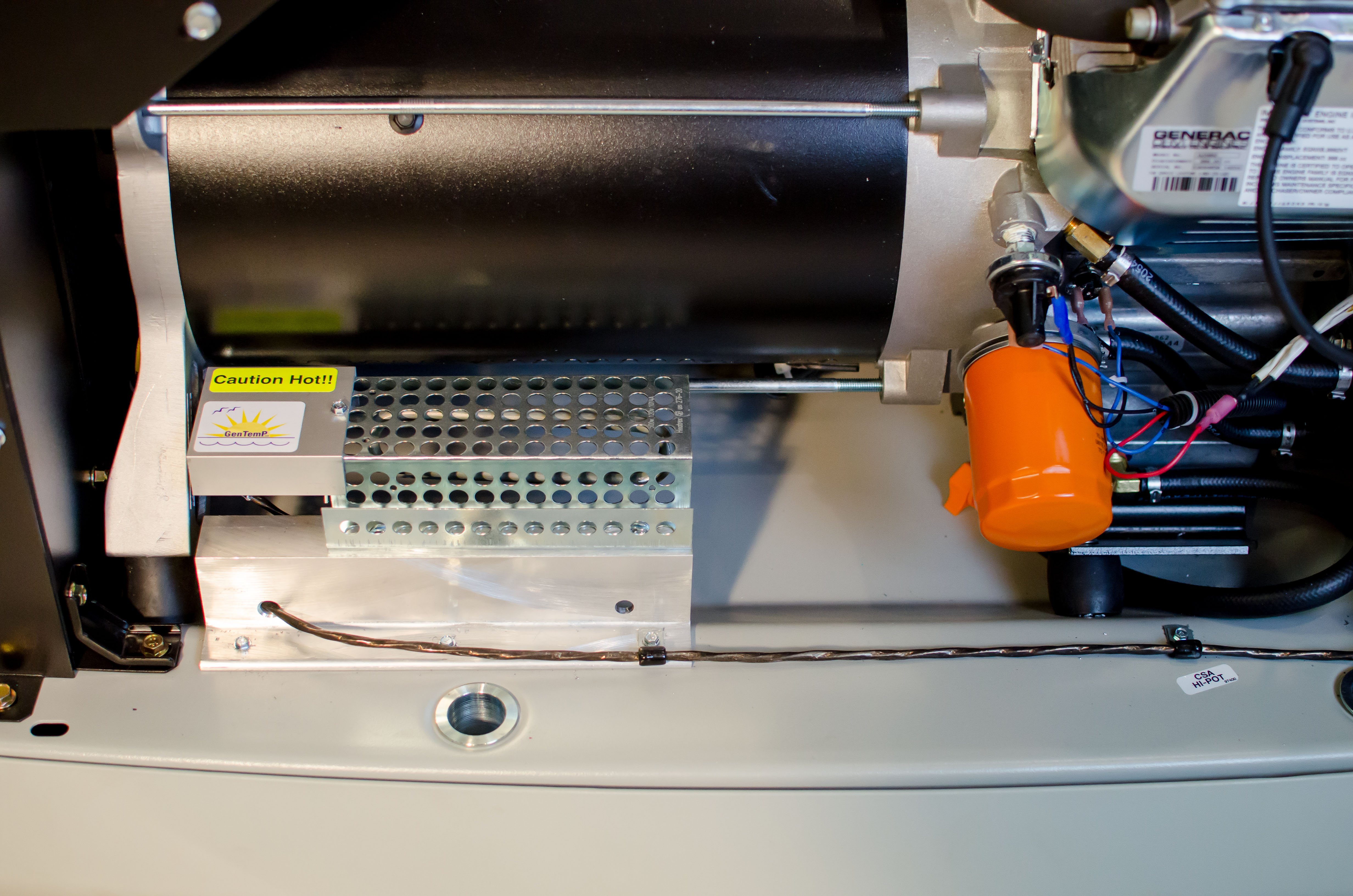
- Mount the GenTemP heat module as shown (figure 1) with 3 of the supplied ¼” x ¾” self tapping screws. On some models, the oil drain hose and wire harness will need to be slightly relocated to maintain a minimum of 3″ cleareance to the heat module. Locate the (2) 1 hole wire looms as shown and secure with (2) ¼” x ½” self tappers supplied.
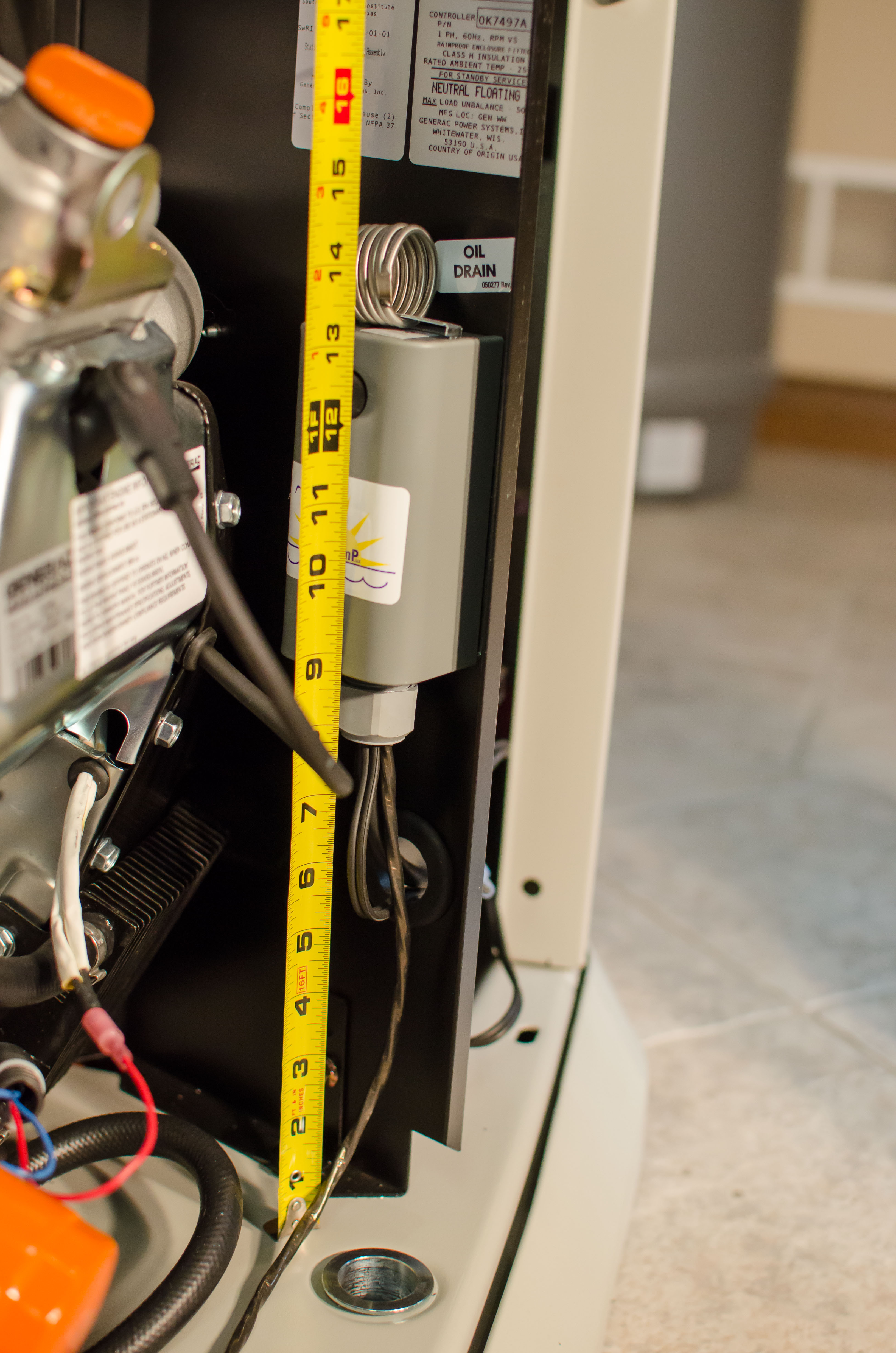
- Mount the GenTemP thermostat as shown (figure 2), 8-9″ up off the base with the (2) remaining ¼” x ½” self tapping screws. On some models, the oil drain hose will need to be relocated as shown. Set the dial on the stat to its lowest setting.
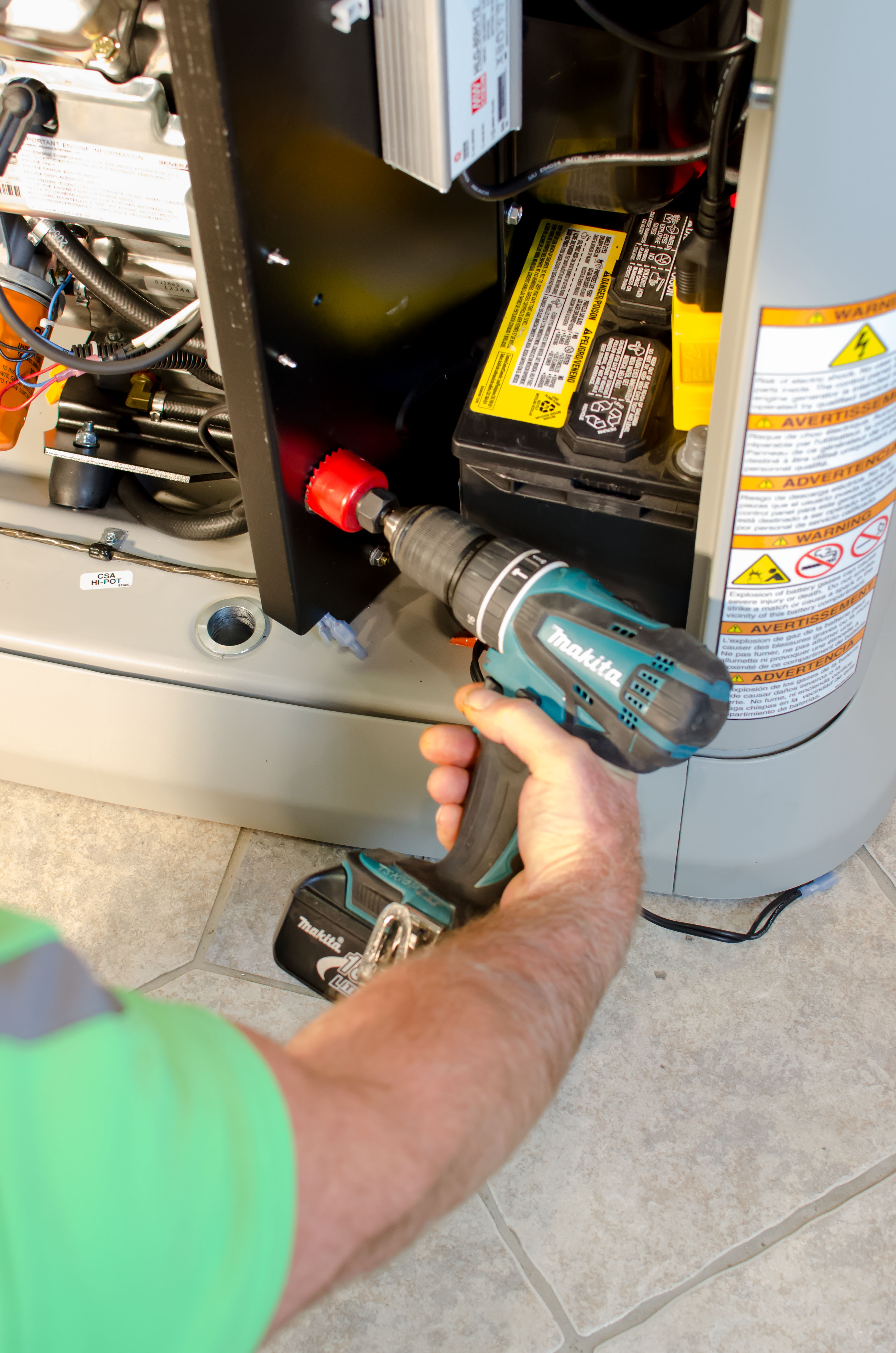
- Carefully drill or knock out punch a 1 ¼” hole 5″ up from the base, centered under the thermostat as shown (figure 3). Install the 1 ¼” rubber grommet in the hole.
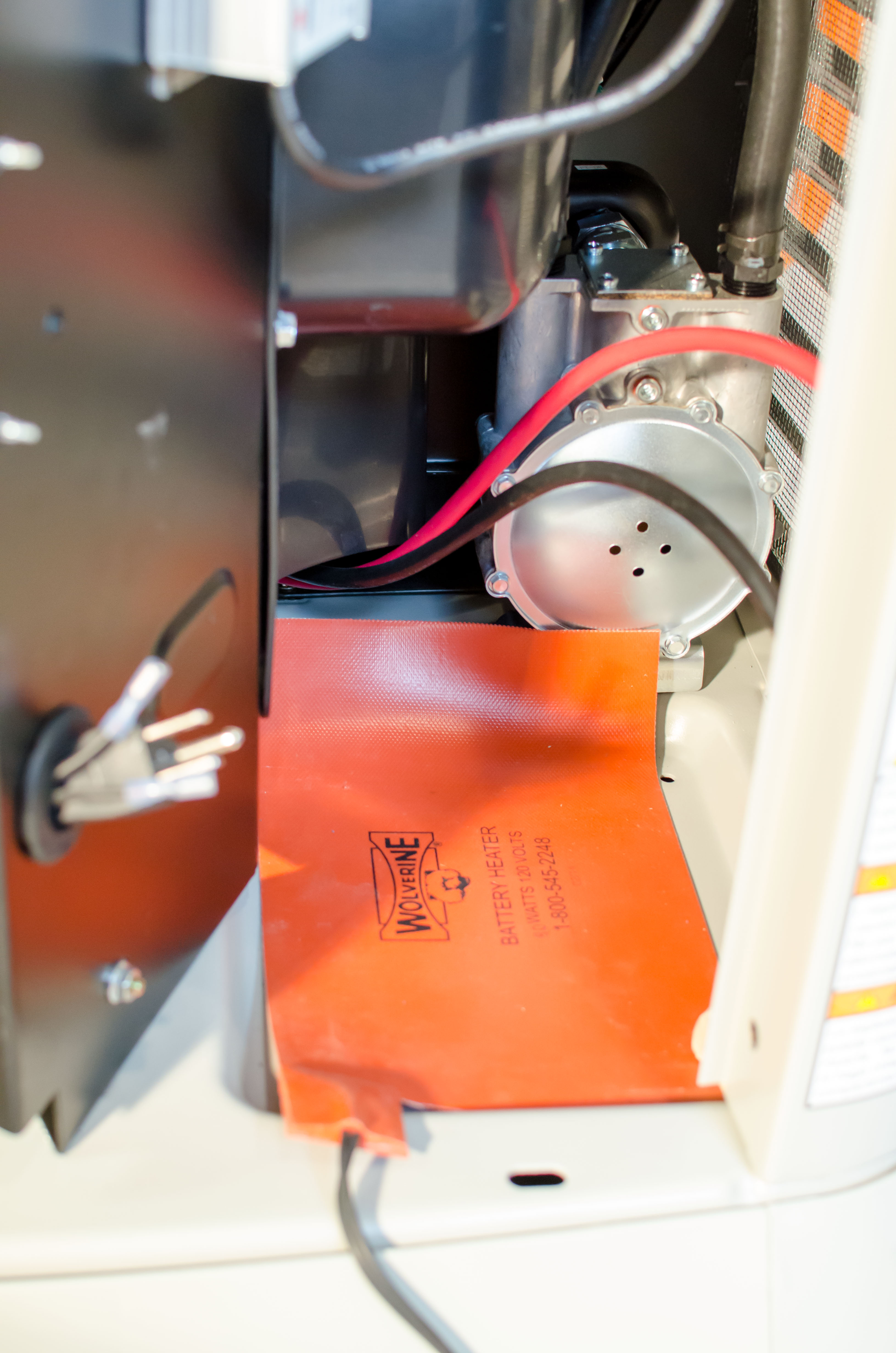
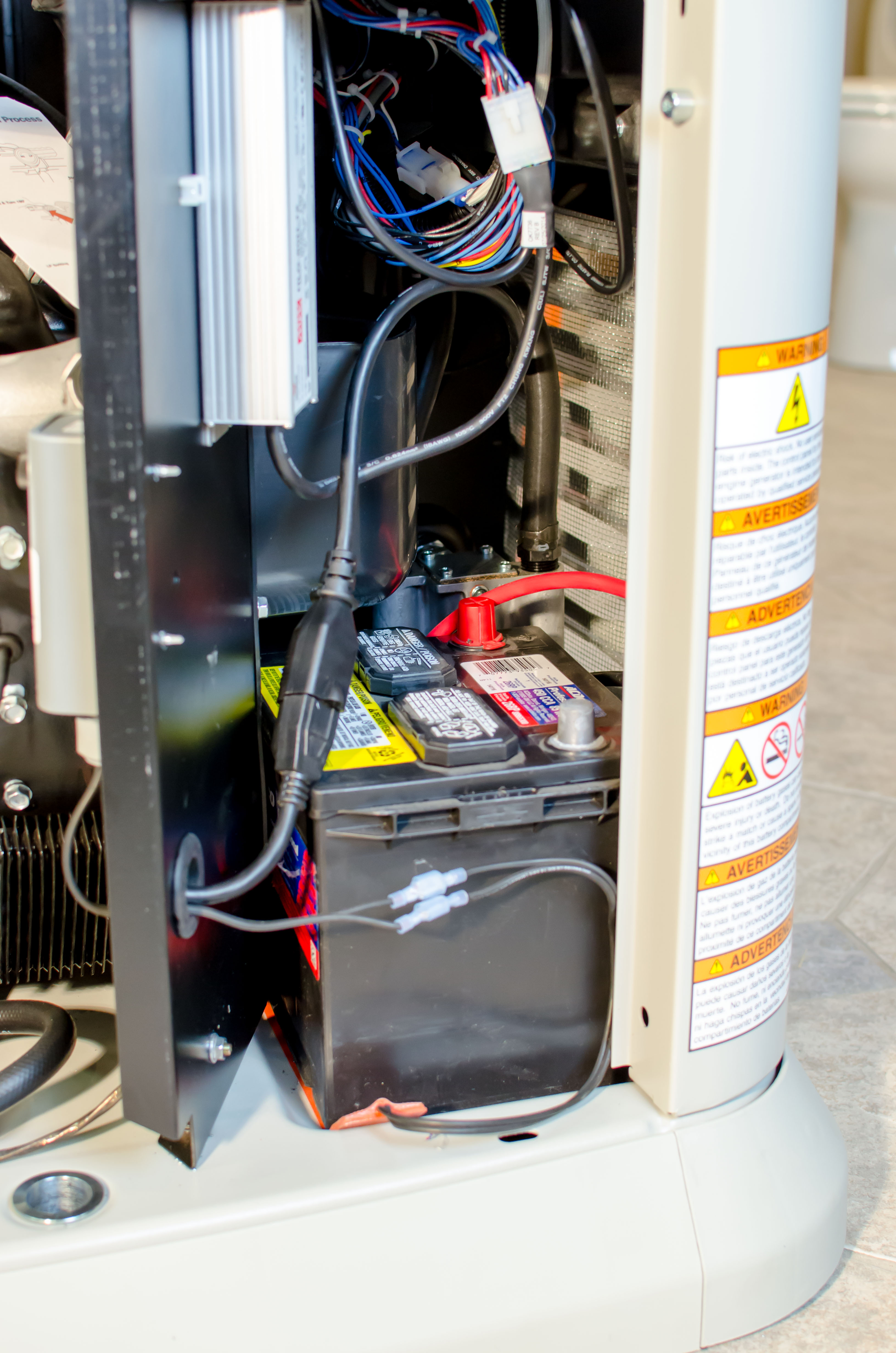
- Remove the battery and place the battery heater pad as shown (figure 4) with the excess lenth rolled up against the gas regulater behind the battery. Replace the battery.
- Remove the screws attaching the control panel and lift it out of the way to access the wire connections area. Provide a 120 volt 3 wire 20 amp circuit to the battery compartment and splice on the supplied 36″ female cord end, leaving that female cord end located near the front of the battery. Reattach the control panel.
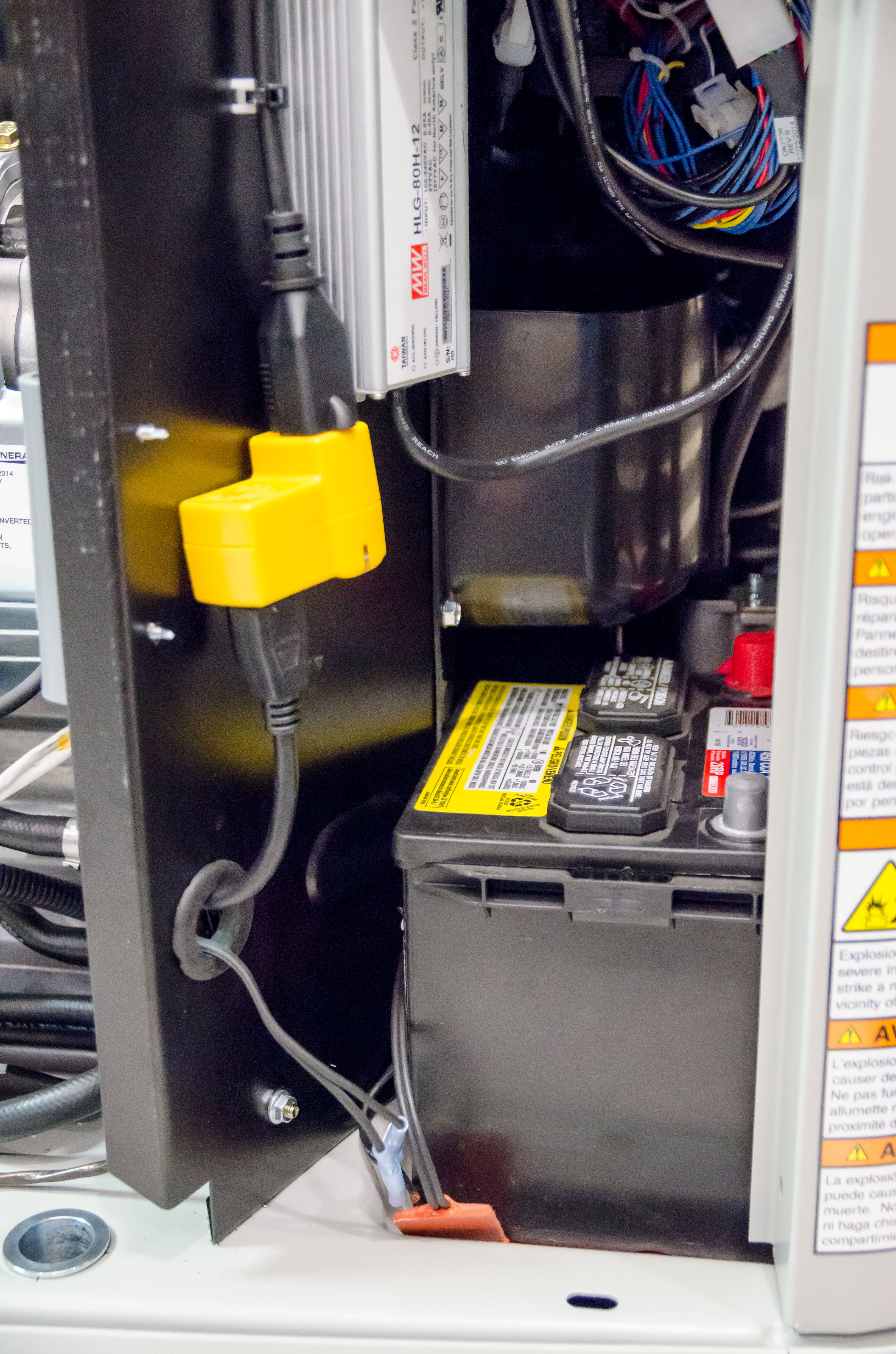
- Route the 3 prong male pigtail hanging out of the thermostat through the rubber grommet with the battery pad pigtail. Plug the (2) battery pad wire connectors into the pigtail ends coming from the thermostat (figure 5).
- You are now ready to test your GenTemP’s operation. Plug the 3 prong male pigtail into the matching 3 prong female cord end and energize the 120 volt circuit.
Do Not Touch the Heat Module, instead put your hand within a couple inches above it. Turn the thermostat up until you hear a faint click. Within a few moments you should sense heat radiating up from the module. Anytime the thermostat setting is above the current outdoor temperature, the heat should be apparent. All GenTemPs have been pretested but verify the heater goes on and off as you turn the stat up and down. Set the stat to 45° - Unplug the 3 prong male and female cord ends from each other and insert the Easy Heat High Limit Safety stat in between them. Locate and attach the zip tie bracket as shown (figure 6) and secure the female cord end as shown. The finished installation should resemble (figure 7).
- Return all covers to unit and place the system’s switch to automatic. Your GenTemP low ambient kit will keep your system warm and ready to run all winter long, for pennies a day.
Should you have any questions, please give GenTemP a call at 815-692-4471 and ask for a tech or email us through our contact page.
Please Note* If your system utilizes one of the whole house type transfer switches, a fuse block and fuse are included to aid you in obtaining your 120 volt grounded power circuit.


